Routes
Categories:
6 minute read
Routes configured under Domains determine to which node or cluster the Trustgrid virtual network should route traffic for a specific subnet.
Virtual Network Routes
Routes defined a the virtual network level allow creating a global route table shared with all nodes and clusters attached to the virtual network. This table is then used to evaluate where to send VPN traffic for a specified destination CIDR.
Route Fields
A Route has the following fields:
| Field Name | Description |
|---|---|
| Destination | This will be the name of the node or cluster that traffic will be routed to. This list is auto-populated based on the nodes and clusters in the selected domain. |
| Destination CIDR | This is the CIDR notation of the virtual network that should be routed to the above destination node or cluster. |
| Metric | If there are multiple routes for the same virtual network the metric will determine which route will be used. The lowest number is the highest priority. See the “Automatic Failover” text below. |
| Description | (Optional) This field can be used to provide additional information about the purpose of the route. e.g. it could label a route as a DR route indicating that in normal circumstances it would have a higher metric than a primary route. |
Managing Virtual Network Routes
Adding Virtual Network Routes
- Navigate to Domain > Virtual Networks and select the desired Virtual Network.
- The Routes table is selected by default
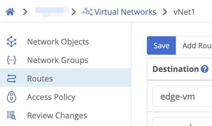
Virtual Network > Routes Tip: Use the search field to filter the list of routes so you can see the routes you are adding. You could filter by the CIDR address or part of the destination node/cluster names. This will show any existing matching routes, and will make it easy to see the new routes you are adding. - Click the add route button.
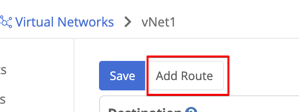
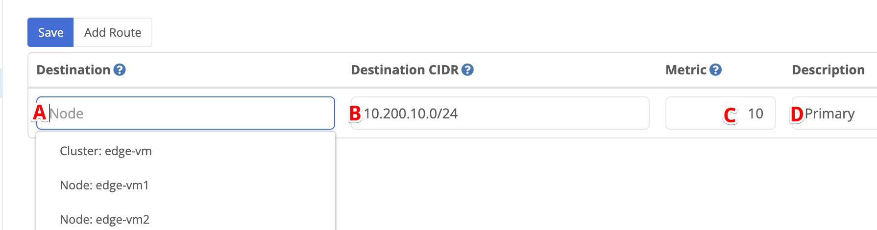
Add route button - Provide the desired route information in the fields
- Select the destination cluster or node
- Enter the destination network in CIDR notation. For a single IP use /32.
- Enter a metric between 1 and 200.
- Optionally, provide a description.
- Repeat the above two steps for any additional routes you wish to add.
- Click the Save button.
Save route button - There should be a notification saying “Routes Updated” but you will need to review and apply changes before the changes are actually be published to nodes in your environment.
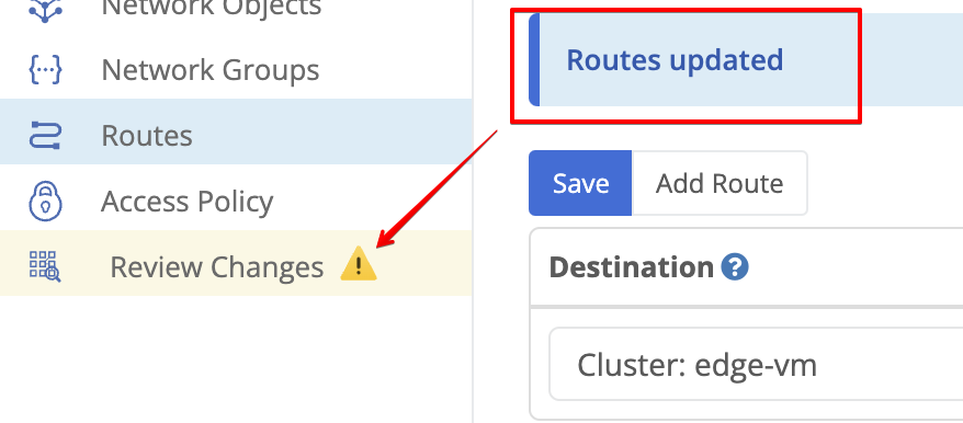
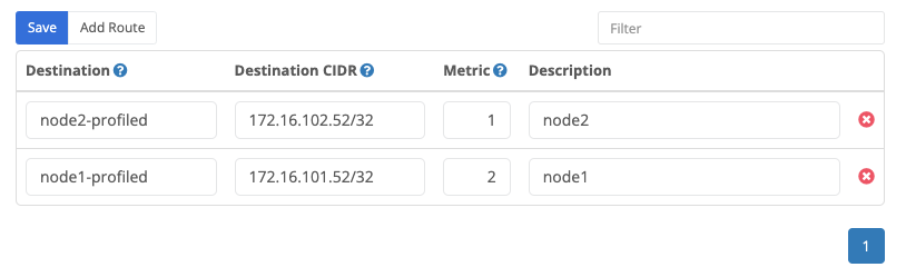
Example of a saved route
Deleting Virtual Network Routes
- Navigate to Domain > Virtual Networks and select the desired Virtual Network.
- The Routes table is selected by default
Virtual Network > Routes - Use the search field to filter the list of routes.You could filter by the CIDR address or part of the destination node/cluster names. This will show any existing matching routes, and will make it easy to see the new routes so you can delete them.
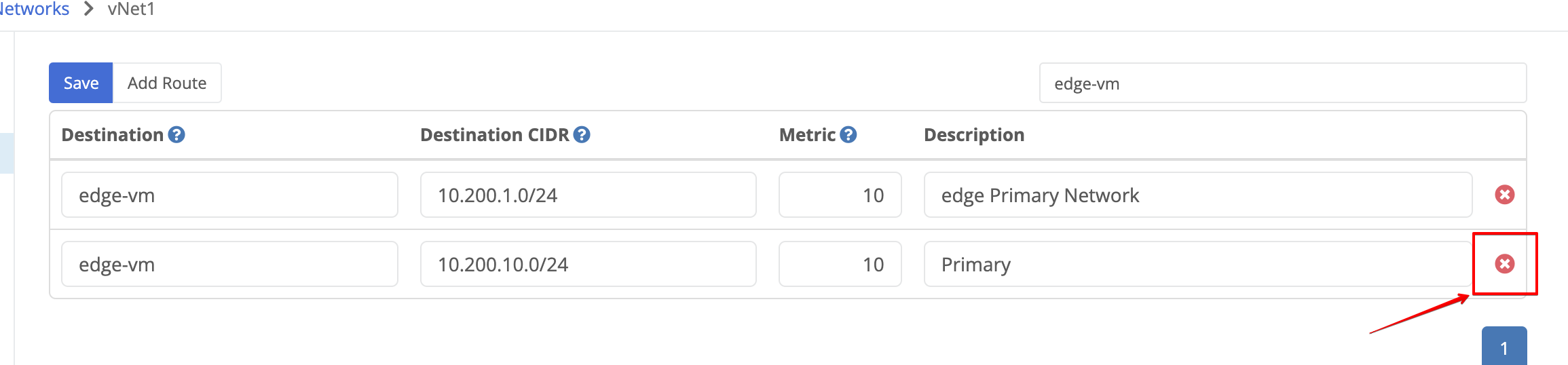
- Click the red X on the far right of the route being removed.
- Repeat the above two steps for any additional routes you wish to add.
- Click the Save button.
Save route button - There should be a notification saying “Routes Updated” but you will need to review and apply changes before the changes are actually be published to nodes in your environment.
Example of a saved route
Route Failover
Route failover allows a subnet to be routed to an alternate node or cluster in the event of a failure. This can be automatic or performed manually.
Prerequisites
In either configuration, the virtual network settings under VPN settings for the primary and backup destination nodes/clusters must match. Including:
Network Virtual Route
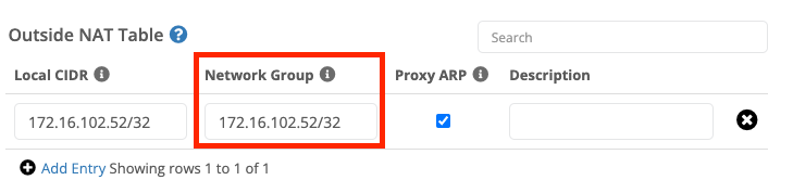
Network Group under Outside NAT Table
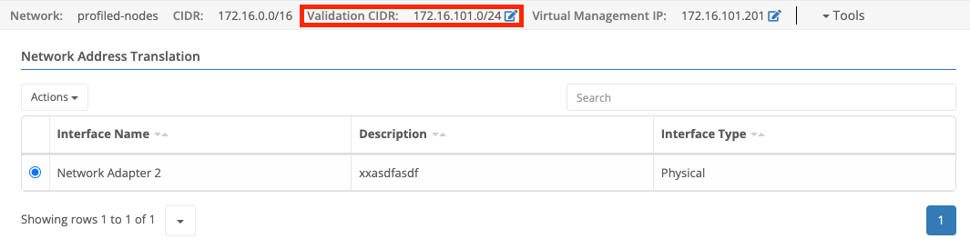
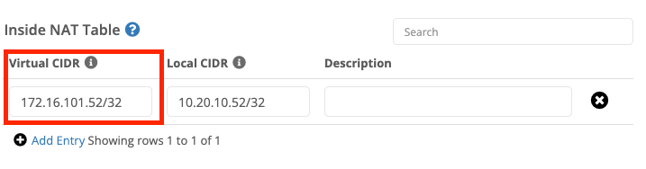
Virtual CIDR under Inside NAT Table
Automatic Failover
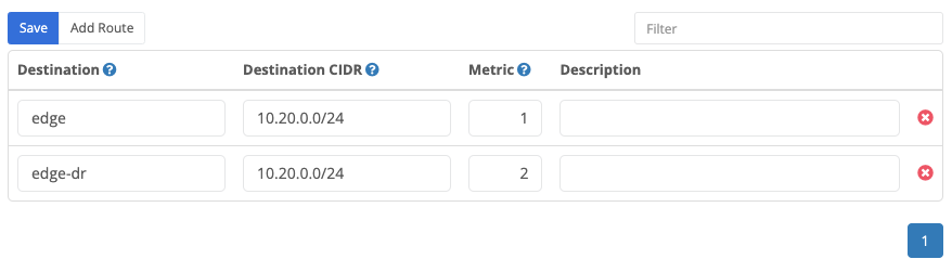
To have the route failover without manual intervention you must define two routes for the same subnet (Destination CIDR) with different metrics. The lowest numerical metric will take precedence unless the destination node or cluster is offline.
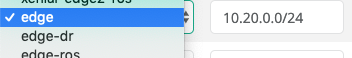
In the below example configuration we want traffic for the 10.20.0.0/24 network to the edge cluster first, and failover to the edge-dr cluster.
Preventing Automated Failback or Forcing a Failover
As mentioned above if multiple routes are configured traffic will route to destination with the lowest metric number. So if the primary destination fails but then comes back online traffic will be routed back automatically.
However, there are some circumstances where this is not desirable. For example, if the primary site is unstable you may wish to keep traffic at the backup site until the primary is stabilized. Alternately, you may wish to preemptively reroute traffic to the backup site in advance of planned maintenance at the primary site.
To preemptively reroute traffic to the backup site, update the backup route to have a lower metric than the primary route.
Route Monitors
Route monitors can also be configured on virtual network routes. Domain-level support for route monitors was added in the June 2025 cloud release.
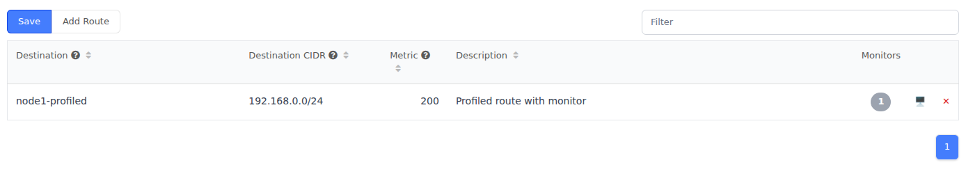
Route monitors at the domain level use the same monitor settings available on node or cluster static routes:
- ICMP or TCP monitoring
- destination IP
- destination port for TCP monitors
- monitor interval
- failures count
- optional maximum latency
Important Domain Workflow Difference
On domain routes, route monitor changes are staged with the route change set. After adding, updating, or deleting route monitors you must still save the route changes and then review and apply changes before the updated monitor configuration is published to nodes.
Notes
- Route monitor traffic still runs from the node or cluster that owns the route after the domain changes are published.
- If the node does not have the required virtual network connectivity or a usable virtual management IP, the monitor may not behave as expected.
- If you have multiple routes for the same destination CIDR, route monitors affect which routes are considered available for traffic.
For monitor behavior, limitations, and recommendations, see Route Monitor Best Practices.
Manual Failover
In some circumstances, it may be preferable for failover to only occur with manual intervention. In this situation, you will have a single route under the domain. To initiate a failover you’ll need to update the destination cluster/node.
- Login to the Portal and select your domain.
- Click the link to the desired domain under the “Name” column.
- Scroll down to the “Virtual Networks” section and select the “Routes” tab.
- Find the route you wish to failover.
- Update the destination device. (e.g. in the below you would switch from edge to edge-dr).
- Click save.
Feedback
Was this page helpful?
Glad to hear it! Please tell us how we can improve.
Sorry to hear that. Please tell us how we can improve.